Thursday, 20 October 2011

Attaching the ears to the head


I created the ear in the same way i created the face by drawing lines onto the picture of my face and ear and then drawing them into 3DS Max and the moving into the right 3D postion. I then used tools such as extrude to create parts of the ear you cant see and so that there were enough polygons to then attach it to the head.


To attch the ear i then moved the camer around so that it was inside the head so that i sould see wehere certain parts of the ear should meet up with the rest of the head. As the ear has more polygons around its edge than there are in the head i need to reduce the number of edges. to do this i turned on the vetex snap on tool snd used the create tool in the right hand side panel and then drew in new polygons turning 3 edges into 1. This meant that the ear would fit in alot nicer and not mess up the shape of the head.


I then attached the ear to the rest of the head and target welded the corresponding vetex.


I finally used the vetex of the head and ear to move parts of it around to try and make it look better and more realistic.

Creating the rest of the head


To create the rest of the head i first used the sphere tool to create a ball and then moved it into position with the face.


After creating the ball i then rotated it around so that the polygons going to almost a point where on the sides of the head.


I then resized and shaped the sphere to match the shape of my head and changed the number of segments in the sphere to match the number of lines coming up from the face so that it would smoothly follow into each other. This makes it alot easier later on when trying to attach the sphere to the face.


As i dont need the whole sphere i next converted the sphere into an editable poly and selected all the polygons that i didnt need using the grow tool and paint selection tool. I then deleted these sections.


Using the existing polygons i then used the soft selection tool to move the points that would attach to the face to the correct position. To do this i turned on the vetex snap on tool on the top menu and moved each point to the correct position.


With the top of the head all lined up i then reduced the amount of polygons in the sphere by selecting every other edge along the side and then using the ring tool to select all the corresponding lines across the head. I then used the collapse tool found in the right hand menu this reduces the amount of polygons in the head and will make it easier to work with and render at the end making the file a smaller size.


To finish off the head i then attached to the face and welded it to the face by using the weld tool. I then draged across and down the edges of the head by holding shift and drag a new polygon out. I then used the target weld tool to make sure all vetex were attached to both the head and the face. I carried this on to create the side of the head and the neck as well as part of the shoulders that could be seen.

Tuesday, 18 October 2011

Mirroring the face and Smoothing it


Once i was happy enough with the 3D nidek of half of the face i then used the symmetry tool to create the other side of the head. To do this i selected the model and under the modify tab i selected symmetry in the drop down box.


At first this tool may slight mess up your model as the symmetry line and the mirrored image may not be in the right place. To move the symmetry line i simply clicked on the + button next the the symmetry tool i added and then selected the mirror line in the drop down tree below the symmetry tool. This allows you to move the symmetry line into the right place. However to start with moving this into the correct place made my model disapear as it was trying to create the image on the wrong side. To create this i ticked the flip option which then created the image on the corrected line. luckily the mirror line was already on the right plane so therefoeee did not have to change this option.


After correcting these problems this is how my model looked. Producing this showed how certain areas of the face were not quite right, like the nose, and therefore used the vetex to corrected this by slightly moving certain parts of the face until it started looking better.


With the symmetry sorted out i then used the turbosmooth tool under the same tabs as the symmetry tool to smoothen the face out and moake it look more realistic. This again showed that certain parts of the face did not look right and therefore i had to go back and try and correct these issues.

Turning 2D frame into 3D model


With the vetex button selected on the right hand side i selected all of the vetex in my model and welded all the points together by using the square button next to the weld tool and the clicked ok. This means the object is now one sold model rather than lots of dettached squares.


Once the model has been welded together i made the mirror line on my model straight to make it easier to mirror the other side. This is simply done by selecting all the on the right hand side and then using the planar tool to put them in line. This tool has three planes to aline the points, for my model i used the X plane.


With these points still selected i then draged them out to somewhere near the edge of the side view of my face. I then moved each point out individually to line up with the side view of my face. I only moved each of the points in 1 direction so that thy do not move out of place from the front view of the face.


By pulling out each of points to near enough the right position creates a model like this. The hardest part of the face to create if the eye as you cannot see the inside part of the eye from the 2 pictures. Therefore this part has to be guessed and got as close to the real thing as you can.

Creating 2D Frame


Once the Photoshoped image of my head was imported into 3DS Max i could now start producing the 3D model. To start i used the line tool under shapes menu to draw over the red lines i had created on my face in photoshop. After drawing the very first square i then turned the snap on toggle tool to make sure that the next square i drew would attach to the first one and so on. To make sure the settings of the snap tool were how i desired i right clicked on the snap toggle button and another menu comes up as shown in the picture above. On default 3DS Max has the grid points selected this needs to be deselected and the vetex points needs to be ticked. This makes sure that all the corners of each face will be connected.


With the whole mesh draw using squares i then selected one of these squares and turned it into an editable poly by right clicking it and using the convert tool and convert the selected square to an editable poly. This will fill in the square and turn it into an object rather than just a line.


While this square is still selected i then used the attche tool under the modify menu on the right to attach all the other squares to make one object. This is easily done by clicking the sqaure box next to the attach tool whihc brings up another menu. In this menu will show you all the different parts that are currently selectable. I wanted to select all the objects therefore just used the select all button and then clicked ok. This then automatically turns each of the squares into an editable poly ready to be turned into a 3D model.

Wednesday, 5 October 2011

Importing the 2D image into 3DS Max


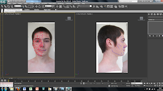
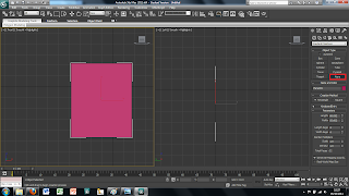
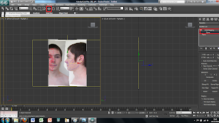
To transfer the 2D image in to 3DS Max first we created a plane using the plan tool in the 2D drawing tools on the right hand side. This plane can just be drawn free hand as long as it is in the right kind of shape.


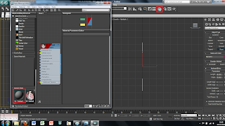
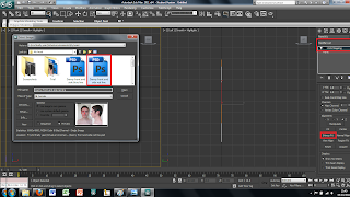
Once the plane is drawn the image we created earlier can then be placed onto this plane. To do this I first clicked on the material tool on the top tool bar. This brings up a new window. In this window there are spheres that represent different materials, at first all of these materials will be grey. To change this to the image I produced earlier simply double click on the material and use the bitmap tool. This will open up another window to add an image file to the sphere. Simply chose the correct image and load it and apply to the plane. At first the plane will change to a grey colour rather than the image this can be fixed by clicking the show image in view port in the material window, this will show the image in the main screen in 3DS Max.


Although the image has been placed into the main screen of 3DS Max the picture is distorted to fit it into the plane sze. This can easily be fixed by using a modifier on the plane. To do this I selected the plane and added a UVW modify found in the modify panel. This will bring up alot of different options on the right hand side. The tool i used was the bitmap fit tool which brings up another window, in which is the folder and image file. I then selected the corresponding file this then sets the image size to the right size. However this makes the picture larger than the plane size therefore the picture needs to be moved to fit correctly into the plane.


To do this i simply used the UVW modify the i used earlier and used the Gizmo tool in the drop down menu. This allows you to move the image freely around the plane so that I could place it into the right place. The plane, however, was also too small therefore, to change the size of the plane, I clikced on the plane and on the right there are tools for the height and the width so i changed these settigns until the plane was the right size.


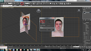
So far I have only imported the face on view of the image. To create the side view is easily done by selecting the plane and then using the select and rotate tool. This brings up rings around the image to rotate it around. To create a copy of the plane simply hold shift while rotating the plane 90 degrees. This creates a copy of the plane and the image all that needs to be down is move the image on the new plane to show just the side view of the face. Each plane can then be moved into place to where I wanted them to be.

Creating usable 2D pictures


To create a 3D model of our own heads on 3DS Max we first had to take pictures of the front and sides of our heads. Once we had suitable pictures to do the job we loaded them onto Adobe Photoshop to undo any distortion created by the camera. To do this, once the picture is loaded into photoshop, we used the lens correction tool found in the Filter, Distortion tool bar. This then brings up a new window as shown above. Then using the tools at the side such as remove distortion and the perspectives to remove any distortion that may have been made taking the picture. This is done as the person taking the picture may have had the camera at an angle and the camera itself slightly distorts the image. All of this is done by eye until it looks right to the user.

Once the lens correction has been applied to both the images they need to be put together onto the same canvas, this is easily done by dragging 1 image from its window to the window with the other image in. as the canvas size will be to small for the 2 images you need to change the canvas size. This is easily done by going into view then canvas size and changing the percentage size to 200 under the width row. This gives enough space for both the images next to eachother on the same canvas.

With both the images on the same cavas we then started to draw in some basic lines that follow the shape of our faces. For this we used the brush tool on the left hand side in a bright blue colour so that the lines can easily be seen.

Finally, to finish modifying the images, we created a mesh over the top of half of the face using the brush tool but in red this time to contrast with the blue. This red mesh is more detailed and tries to follow the line of the face trying to mimic the direction of the muscles in the face. This should make it easier to create the 3D image as all the lines should more or less be in the right place before we'ev even begun.