Friday 21 October 2011

Creating bump map


To create the bumpbitmap i first desaturated the image so that it was turned into a black and white image.


I then used the high pass tool found in the filter tab to turn the image into dark and light areas to make the bump effect in 3DS max more accurate and realistic. I set the pixcels to 0.8 as i didnt want the bump effect to create to much of an uneven surface.


To then add the bump effect to the face, in the materials editer, i added the bitmap file to the bump effect in the maps tab. To begin with this creates to much of a bump so i added a mix onto the material as well and had the bitmap as the first colour and then added a noise material as the second. This softens the bump and makes it look more realistic.

Creating the face bitmap


Using the rendered uvw map i made in 3DS max i opened it into photoshop and added a blue layer over the top. I then hid the blue layer and pressed control A to select everything and then control c to copy it.


I then made the blue layer visible and made sure i had that layer selected. I then used the quick mask tool on the bottom left hand side and pasted the image into the blue layer. This created a line drawing of my map in this layer.I then made the border of the line drawing thicker so that it could be seen more easily.


I then used the create mask layer at the bottom of the layers panel to create a mask making the lined drawing the thing visible with a clear back round. To finish this layer i then right clicked the mask part of the layer and chose to add mask layer. This finalises the layer and turns it back into a normal layer.


With my template layer complete i then opened my file with the picture of the front and side of my head so that i can create my face as a mask. To do this i used the laso tool to select different parts of my face.


I then copied and paste this shape into my mask file and resized and shaped it to fit into the section of the mask i wanted it to. I carried on these steps to start filling in the mask and recreate my face.


As all the parts may not fit together perfectly and leave seams and line were the colours dont match up properly i used the copy stamp tool to blend some parts into each other. This is done by holding Alt and clicking on an apropriate section colour and then clicking and dragging over the seam to bland them into each other. Although this works well if you go over a seam a few times the colour tends to become blurred and you can lose the quality of the pictrue.


Another tool i used to blend each section into each other was the patch tool. This uses the texture of other parts of the face to blend other sections into each other. This is used like the laso tool in that you first drag over a clean area and then click and drag the section over a seam to blend each section into each other. This tool dosent blur the image so is better to use rather than the stamp tool. Whilst doing this i uploaded the unfinished mask into 3DS max to see how the face was looking on my model. This is helpful as when ever you make changes in photoshop and then save it you can see what effect this has on the model as it changes in 3ds max straight away.


The final tool i used to make sure that the mask fit onto my model how i wanted i used the liquify tool found under the filter tab. This brings up another window in which you can slightly move the features of the face by stretching the image. I used this to slightly move my mouth so that it was in the right poistion on my model.

Thursday 20 October 2011

UVW Unwraping


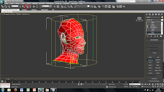
To create the right material for my head i first had to create a template so that the picture of my face would sit perfectly on the model. To do this i used a tool called UVW unwraping which is found in the drop down menu and the modify menu, making sure that i had the editable poly section highlighted. This tool helps create a flat version of the 3D model so that all the polygons can be seen. For this tool to work i had to create 2 templates one for the head and 1 for the ear as the ear is a very complex shape. So to do the head i first used the paint selection tool to select every polygon in the head apart from the ear.


I then used the cylindrical tool so that the uvw mapping tool knows exaclty what i want to be flattened out. I resized this tool so that the whole head was inside the yellow cylinder. Once i had done this i then deselected the cylindrical tool and went into edit.


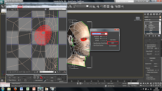
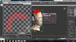
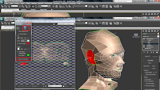
This brings up a new window in which the uvw mapping tool has tried to flatten out the model. Although it has flatten out most of it certain sections of the head where polygons overlap havent been flattened out how we want them. One area that this is very apparent is the eye, so to sort this out i used the face selection tool to select the face within the eye socket. I then went into the tool menu and used the relax tool. This brings up another menu and in this menu i changed the drop down menu to relax by centres and clicked apply a couple of times until i was happy with how it had flattened out the eye. I used the same technique for the nose.


Another area that didnt turn out quite how i wanted it to was the top of the head. All of the polygons in this area were far to close together. To solve this problem i used the same tool as before but instead of relaxing it by centres i changed it to relax by edges. I then relxed the area i wanted a couple of times again until i was happy with it. I also used the vetex selection tool to move certain areas that were oddly shaped or too close together and manually moved them myself until i was happy with how it looked.


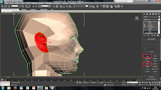
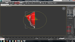
I then moved onto mapping the ear. I first selected the ear by using the paint selection tool again but instead of using the cylindrical mapping tool i used the planar tool and selected the x plane. This creates a yellow box surrounding the ear. I then deselected this tool and used the pelt tool.


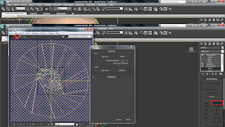
This brings up another window showing the ear and how it will be pulled out. I selected the outa ring where the ear was being pulled out to and moved it slightly to better line up and moved it out further so that the ear would be completely pulled out in the right way. I then used the start relaxing and pelt buttons to see how it would be pulled out until i was happy with the result. I then finalised this by cllicking on the commit button at the button. And then went back into the edit window to moce the ear map away from the head so that they werent over lapping.


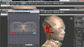
Making sure i had the symmetry section highlighted on the right hand side i then added another uvw unwrapping modifier. This will then create the map for the other side of the head as well however to begin with they will be overlapping. Tos sort this out i first went into the edit panel and in the new window selected the right hand side of the head and used the mirror tool to make sure it was the right was round and the moved to along side the left hand side. i then welded each side to each other across the seam to create one map. I did the same with the ear however didnt wled these together as they are not attached to each other.


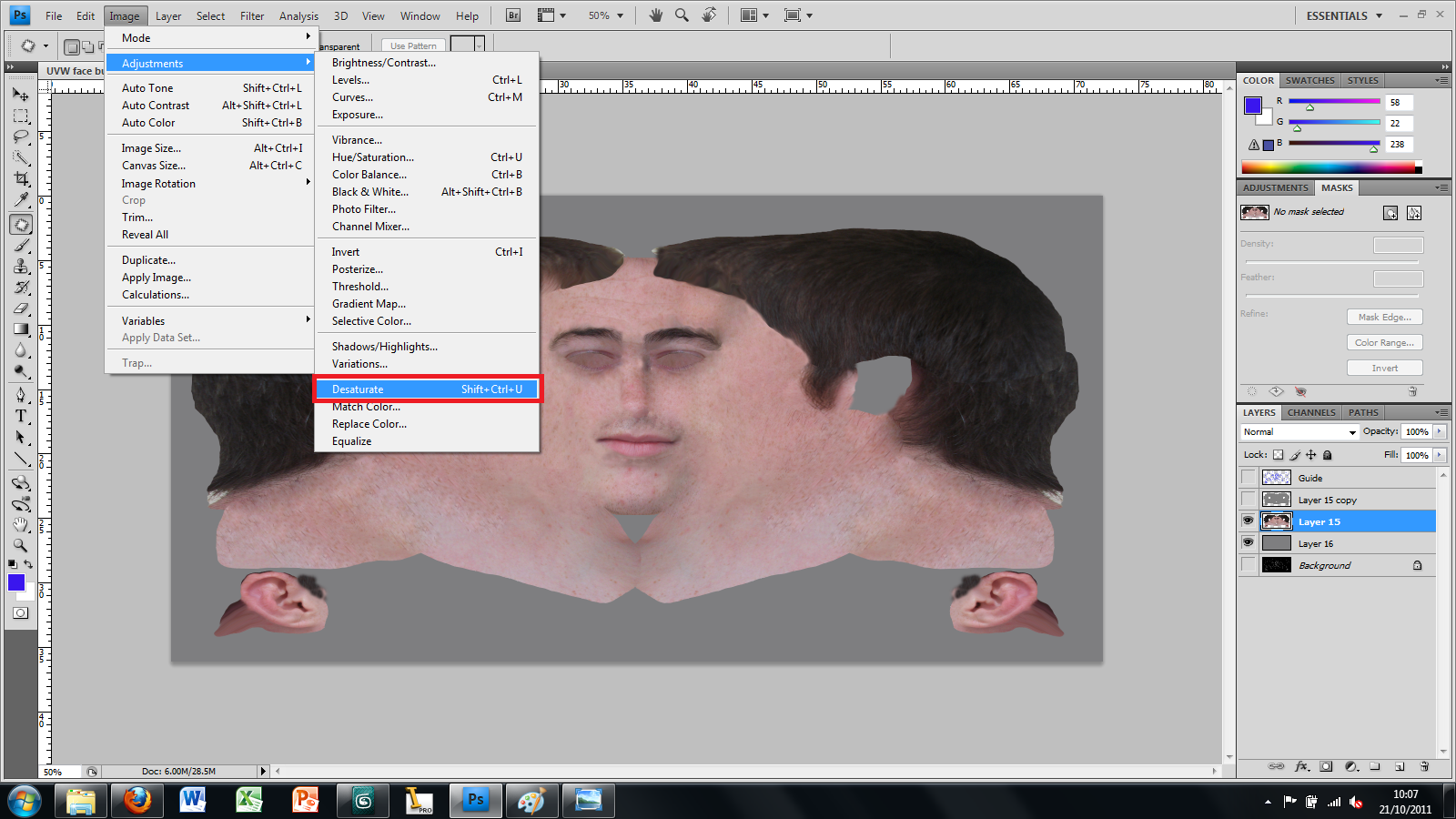
Once i had the mapping of the head done i then wanted to render the image out so that i could use it in photoshop. To do this i used the render tool in the tool menu. This first brings up a new window asking you what size and how you want to render out the image. I chose to set the proportions of the image as 2048 by 1024. I then hint render.


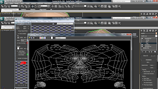
The image that rendered out was a black and white lined image of the map i had created.

Attaching the ears to the head


I created the ear in the same way i created the face by drawing lines onto the picture of my face and ear and then drawing them into 3DS Max and the moving into the right 3D postion. I then used tools such as extrude to create parts of the ear you cant see and so that there were enough polygons to then attach it to the head.


To attch the ear i then moved the camer around so that it was inside the head so that i sould see wehere certain parts of the ear should meet up with the rest of the head. As the ear has more polygons around its edge than there are in the head i need to reduce the number of edges. to do this i turned on the vetex snap on tool snd used the create tool in the right hand side panel and then drew in new polygons turning 3 edges into 1. This meant that the ear would fit in alot nicer and not mess up the shape of the head.


I then attached the ear to the rest of the head and target welded the corresponding vetex.


I finally used the vetex of the head and ear to move parts of it around to try and make it look better and more realistic.

Creating the rest of the head


To create the rest of the head i first used the sphere tool to create a ball and then moved it into position with the face.


After creating the ball i then rotated it around so that the polygons going to almost a point where on the sides of the head.


I then resized and shaped the sphere to match the shape of my head and changed the number of segments in the sphere to match the number of lines coming up from the face so that it would smoothly follow into each other. This makes it alot easier later on when trying to attach the sphere to the face.


As i dont need the whole sphere i next converted the sphere into an editable poly and selected all the polygons that i didnt need using the grow tool and paint selection tool. I then deleted these sections.


Using the existing polygons i then used the soft selection tool to move the points that would attach to the face to the correct position. To do this i turned on the vetex snap on tool on the top menu and moved each point to the correct position.


With the top of the head all lined up i then reduced the amount of polygons in the sphere by selecting every other edge along the side and then using the ring tool to select all the corresponding lines across the head. I then used the collapse tool found in the right hand menu this reduces the amount of polygons in the head and will make it easier to work with and render at the end making the file a smaller size.


To finish off the head i then attached to the face and welded it to the face by using the weld tool. I then draged across and down the edges of the head by holding shift and drag a new polygon out. I then used the target weld tool to make sure all vetex were attached to both the head and the face. I carried this on to create the side of the head and the neck as well as part of the shoulders that could be seen.

Tuesday 18 October 2011

Mirroring the face and Smoothing it


Once i was happy enough with the 3D nidek of half of the face i then used the symmetry tool to create the other side of the head. To do this i selected the model and under the modify tab i selected symmetry in the drop down box.


At first this tool may slight mess up your model as the symmetry line and the mirrored image may not be in the right place. To move the symmetry line i simply clicked on the + button next the the symmetry tool i added and then selected the mirror line in the drop down tree below the symmetry tool. This allows you to move the symmetry line into the right place. However to start with moving this into the correct place made my model disapear as it was trying to create the image on the wrong side. To create this i ticked the flip option which then created the image on the corrected line. luckily the mirror line was already on the right plane so therefoeee did not have to change this option.


After correcting these problems this is how my model looked. Producing this showed how certain areas of the face were not quite right, like the nose, and therefore used the vetex to corrected this by slightly moving certain parts of the face until it started looking better.


With the symmetry sorted out i then used the turbosmooth tool under the same tabs as the symmetry tool to smoothen the face out and moake it look more realistic. This again showed that certain parts of the face did not look right and therefore i had to go back and try and correct these issues.

Turning 2D frame into 3D model


With the vetex button selected on the right hand side i selected all of the vetex in my model and welded all the points together by using the square button next to the weld tool and the clicked ok. This means the object is now one sold model rather than lots of dettached squares.


Once the model has been welded together i made the mirror line on my model straight to make it easier to mirror the other side. This is simply done by selecting all the on the right hand side and then using the planar tool to put them in line. This tool has three planes to aline the points, for my model i used the X plane.


With these points still selected i then draged them out to somewhere near the edge of the side view of my face. I then moved each point out individually to line up with the side view of my face. I only moved each of the points in 1 direction so that thy do not move out of place from the front view of the face.


By pulling out each of points to near enough the right position creates a model like this. The hardest part of the face to create if the eye as you cannot see the inside part of the eye from the 2 pictures. Therefore this part has to be guessed and got as close to the real thing as you can.